Core Engineering Takeaways
- •Motors work on magnetism: electric current turns wire coils into electromagnets that push against permanent magnets to spin a shaft.
- •Torque is turning muscle (pushing power), while RPM is spinning speed. When load increases, speed drops and current increases.
- •Brushed DC motors are cheap and simple with just 2 wires, but mechanical brushes wear out and create electrical sparks over time.
- •BLDC (Brushless) motors have no brushes, delivering 90%+ efficiency, ultra-high RPM, and long life—ideal for drones and agile walking robots.
- •Stepper motors move in exact, fixed angle steps (e.g. 1.8° per step), holding their position tightly without needing an external sensor.
- •Servo motors bundle a motor, gearbox, angle sensor, and control circuit together so you can command them to turn to an exact angle like 90° or 180°.
- •Microcontrollers (Arduino, ESP32) cannot power motors directly. You must use a Motor Driver (H-Bridge) to switch heavy battery current safely.
- Basic electrical terms: Voltage (V), Current (Amperes), and Resistance (Ohms)
- Understanding of positive (+) and ground (-) battery terminals
1. How Electric Motors Work (Simple Core Physics)
At its heart, an electric motor is a machine that turns electrical energy into physical spinning motion.
The Magnetic Push & Pull:
Think of holding two refrigerator magnets in your hands. If you bring two North poles together, they repel and push each other away. If you bring North and South together, they attract and snap together.
In an electric motor:
- We place stationary magnets inside the motor casing (called the Stator).
- We wrap insulated copper wire into coils on the spinning shaft (called the Rotor).
- When we pass battery current through these coils, they turn into powerful electromagnets.
- The magnetic push and pull between the coils and the magnets forces the shaft to spin continuously!
The 3 Golden Rules of Motors:
- 1Torque vs Speed (The Trade-Off):
- Torque is rotational muscle (how hard the motor can twist or push heavy robot wheels up a steep hill).
- Speed (RPM) is how fast the motor shaft spins.
- When a robot is driving flat and empty, speed is high and torque load is low. When the robot hits a steep ramp or carries a heavy load, it slows down and demands much higher torque.
- 2Back-EMF (The Natural Speed Governor):
- As the motor spins inside the magnetic field, it acts like a tiny electricity generator.
- It generates an opposing counter-voltage called Back-EMF (Back Electromotive Force) that pushes back against the battery voltage.
- The faster the motor spins, the stronger this push-back voltage becomes. When Back-EMF nearly equals battery voltage, the motor cannot spin any faster. This is why motors have a maximum no-load speed!
- 3Stall Current (Why Stuck Motors Overheat):
- When the motor is completely stopped or mechanically blocked (0 RPM), there is zero Back-EMF.
- With no pushback voltage, the motor pulls its absolute maximum electrical current from the battery. This is called the Stall Current.
- Stall current is often 5x to 10x higher than normal running current. If a wheel gets jammed and stays stalled, the motor and driver chip will quickly overheat and can burn out!
1. Lorentz Force (Electromagnetic Pushing Power)
A motor coil with 0.5m of wire inside a 0.8 Tesla magnet drawing 2 Amps produces: 2 A × 0.5 m × 0.8 T = 0.80 Newtons of push.
2. Motor Torque (Turning Muscle)
If a motor has Kt = 0.05 N·m/A and pulls 3 Amps under load, it produces: 0.05 × 3 = 0.15 N·m of torque.
3. Actual Motor Current & Stall Current
A 12V motor with 2Ω coil resistance has a Stall Current of: 12V ÷ 2Ω = 6.0 Amps. Your motor driver must be able to handle 6A without burning!
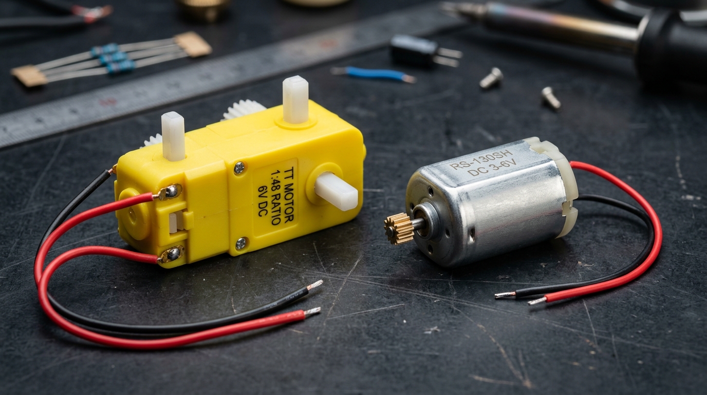
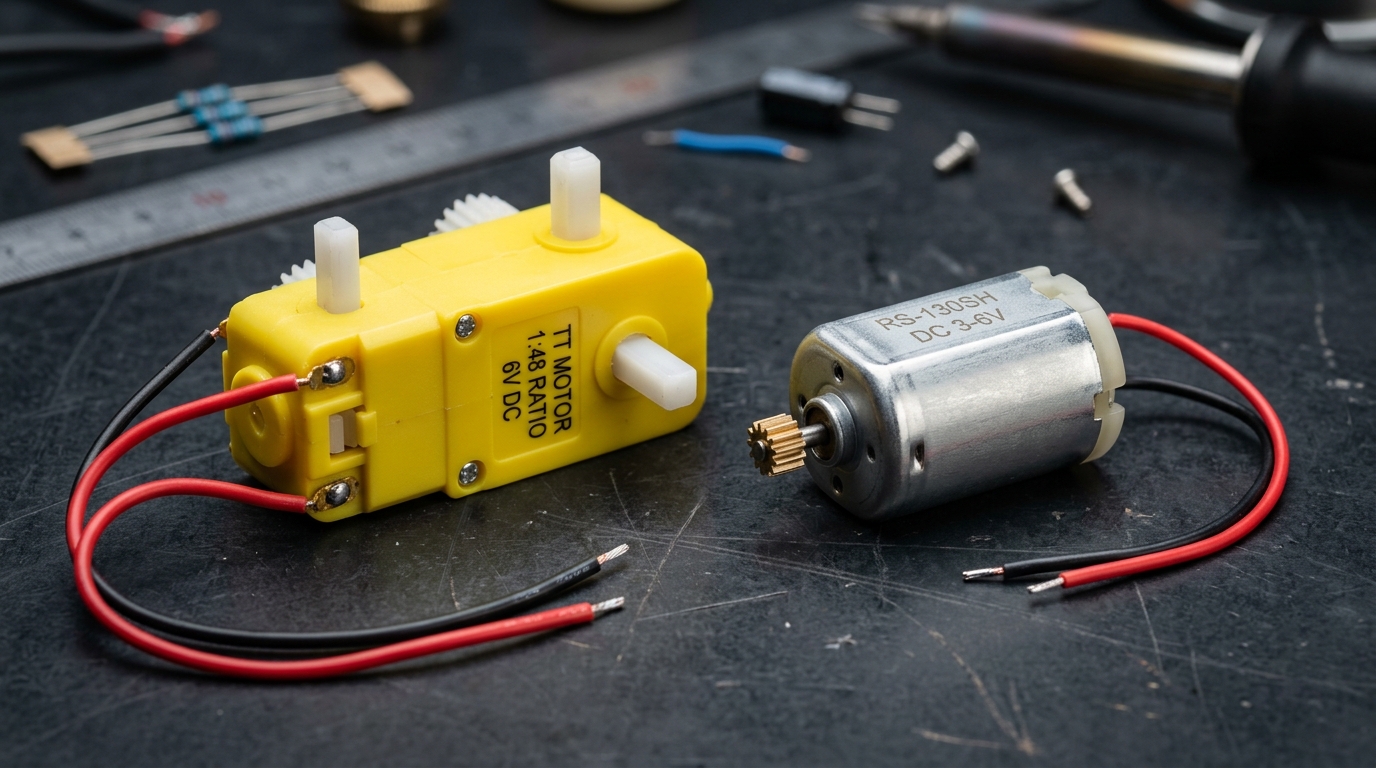
2. Brushed DC Motors (Simple 2-Wire Workhorse)
Brushed DC motors are the classic, beginner-friendly motors used in toy cars, wheeled hobby robots, and simple conveyor belts.
How They Work:
- Two Simple Wires: Has a positive wire (red) and a negative wire (black).
- Forward Rotation: Connect red to (+) and black to (-) to spin clockwise.
- Reverse Rotation: Swap the two wires around to spin counter-clockwise immediately.
- Inside the Motor: Two carbon brushes slide against a spinning copper ring (commutator) to switch electrical current automatically.
Controlling Speed & Direction:
- Speed Control (PWM): Rapidly pulsing voltage ON and OFF thousands of times per second (like a rapid light switch). A 50% duty cycle makes the motor spin at half speed.
- Direction Control (H-Bridge): A motor driver chip electronically flips polarity without moving any physical wires.
Coreless DC Motors (Ultra-Fast):
- Standard motors have a heavy iron cylinder inside.
- Coreless motors use a hollow, ultra-lightweight basket coil with no iron.
- Because there is virtually no rotating weight, they accelerate from 0 to 10,000 RPM in milliseconds!
- Used in micro racing drones, precision surgical tools, and robot fingers.
Pros & Cons:
- Pros: Super cheap, only 2 wires needed, extremely simple to wire and test.
- Cons: Carbon brushes wear out after 1,000–3,000 hours, produce small electrical sparks, and create heat.
Never choose a motor driver based on normal running current alone. When a robot hits an obstacle or starts suddenly, it draws full Stall Current (5x to 10x normal). Choose a driver chip that handles stall spikes safely!
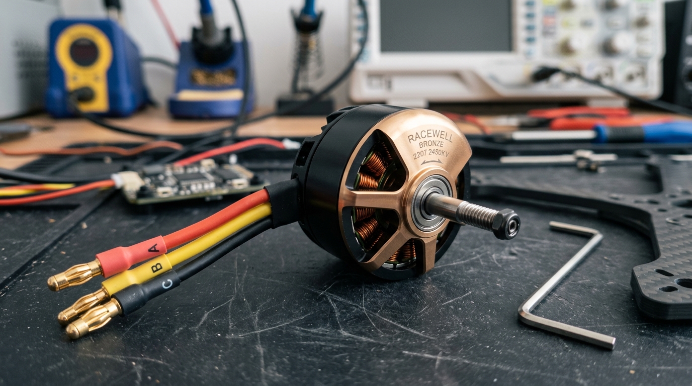
3. Brushless DC (BLDC) Motors (Speed & Power)
Brushless DC (BLDC) motors solve the biggest problem of brushed motors: they completely eliminate the physical brushes!
How Brushless Motors Work:
- The permanent magnets sit on the rotating shaft (Rotor).
- The wire coils stay stationary on the outer shell (Stator).
- Because the wire coils don't move, there are no rubbing brushes to wear out!
- An external controller called an ESC (Electronic Speed Controller) or FOC Driver switches power through 3 phase wires (U, V, W) to pull the magnets around.
Why Brushless Motors Are Superior:
- No Rubbing Brushes: Almost zero mechanical wear and zero brush sparks.
- Over 90% Efficiency: Converts almost all battery power into spinning motion rather than waste heat.
- Crazy Fast Speeds: Easily reaches 10,000 to 50,000+ RPM.
- Runs Much Cooler: Heat escapes directly through the outer metal shell into the air.
Inrunner vs Outrunner:
- Inrunner Motors: The magnet spins inside the closed case. High RPM, lower torque (RC race cars, ducted fans).
- Outrunner Motors: The outer metal bell spins around the coils. High torque at moderate RPM (drone propellers, electric skateboards, robotic dog legs).
What is FOC (Field-Oriented Control)?:
- Standard drone controllers switch power in sudden square blocks, making a buzzing sound at slow speeds.
- FOC is smart software that feeds smooth sine waves into the 3 coils.
- This creates whisper-quiet, vibration-free motion and smooth torque control even at 1 RPM!
#include <SimpleFOC.h>

// 1. Setup 3-Phase Brushless Motor (11 pole pairs)
BLDCMotor motor = BLDCMotor(11);
BLDCDriver3PWM driver = BLDCDriver3PWM(9, 10, 11, 8); // PWM Pins + Enable Pin

// 2. Magnetic Angle Sensor (AS5600 on I2C)
MagneticSensorI2C sensor = MagneticSensorI2C(AS5600_I2C);

void setup() {
  sensor.init();
  motor.linkSensor(&sensor);

  driver.voltage_power_supply = 12.0; // 12V Battery
  driver.init();
  motor.linkDriver(&driver);

  // Set control mode to smooth speed control
  motor.controller = MotionControlType::velocity;
  motor.voltage_limit = 12.0;

  motor.init();
  motor.initFOC(); // Align magnetic rotor with coils
}

void loop() {
  motor.loopFOC();  // High-speed FOC calculation
  motor.move(10.0); // Spin smoothly at 10 rad/s (~95 RPM)
}
Note: Arduino SimpleFOC code demonstrating smooth, closed-loop speed control of a 3-phase brushless motor using magnetic angle feedback.
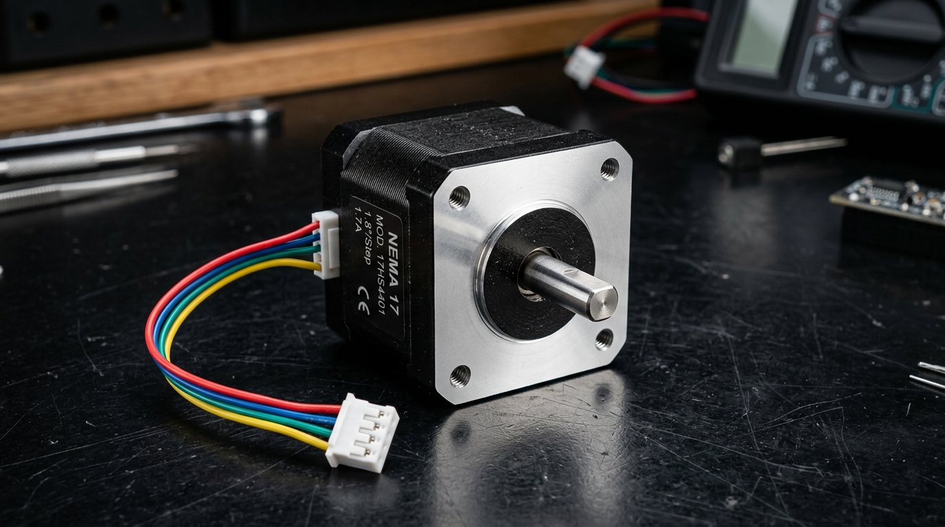
4. Stepper Motors (Precise Step-by-Step Angles)
A Stepper Motor does not spin freely like a fan. Instead, it clicks forward in tiny, exact digital steps.
How Steppers Work:
- Inside the motor is a gear-shaped magnetic rotor and multiple electromagnetic coils.
- Send 1 electrical pulse → the shaft clicks forward by exactly 1.8°.
- Send 200 pulses → the shaft completes exactly 1 full 360° turn (360° ÷ 1.8° = 200 steps).
Why 3D Printers & CNCs Love Steppers:
- Exact Positioning without Sensors: To move a 3D printer nozzle 10mm right, the computer sends 500 pulses. It knows the nozzle moved exactly 10mm without needing an expensive camera or sensor!
- Holding Torque: When stopped with power ON, the magnetic coils lock the rotor tightly in place like a clamp so the nozzle never slips.
What is Microstepping? (Silent & Smooth):
- Full steps can create mechanical vibration and buzzing noises.
- Modern stepper drivers (like the TMC2209) use Microstepping to divide each 1.8° step into 16, 64, or 256 micro-steps using smooth sine-wave currents.
- With 1/256 microstepping: 200 steps × 256 = 51,200 microsteps per revolution for whisper-quiet motion!
Stepper Steps per Revolution Formula
A standard 1.8° stepper requires: 360° ÷ 1.8° = 200 steps per revolution. A high-precision 0.9° stepper requires: 360° ÷ 0.9° = 400 steps per revolution.
| NEMA Size | Faceplate Dimensions | Holding Torque Range | Common Robotics Application |
|---|---|---|---|
| NEMA 11 | 28 mm × 28 mm | 0.06 – 0.12 N·m | Miniature pan-tilt camera gimbals & robotic grippers |
| NEMA 17 | 42 mm × 42 mm | 0.35 – 0.65 N·m | 3D printers (Ender/Prusa), desktop robotic arms, CNC lasers |
| NEMA 23 | 57 mm × 57 mm | 1.20 – 3.00 N·m | Heavy CNC milling machines, warehouse sorting robots |
| NEMA 34 | 86 mm × 86 mm | 4.50 – 12.0 N·m | Industrial palletizing robot arms & heavy factory gantries |
5. Servo Motors (Built-in Brains & Joint Control)
A Servo Motor is an all-in-one smart actuator designed to rotate to an exact commanded angle and hold it firmly.
The 4 Parts Inside Every Servo:
- 1. Small DC Motor: Provides the spinning power.
- 2. Gearbox: Slows down the motor to multiply torque (muscle power).
- 3. Angle Sensor (Potentiometer): Measures the exact angle of the output shaft.
- 4. Internal Controller (The Brain): Automatically adjusts motor power until the horn reaches the requested angle!
Standard Hobby RC Servos (SG90, MG996R):
- Uses 3 wires: Power (+5V Red), Ground (GND Brown/Black), and Signal (PWM Orange/Yellow).
- Send a 50 Hz PWM pulse to command an exact angle:
- 1.0 millisecond pulse → Moves to 0° (Far Left).
- 1.5 millisecond pulse → Moves to 90° (Center).
- 2.0 millisecond pulse → Moves to 180° (Far Right).
Smart Serial Bus Servos (Dynamixel, Feetech):
- For robot arms (6 joints) or humanoid robots (18+ joints), 3-wire servos create a messy rat's nest of wires.
- Smart Serial Servos connect in a single daisy-chain (Servo 1 → Servo 2 → Servo 3).
- Two-Way Communication: You can command angles AND read back real-time position, speed, motor temperature, and torque load!
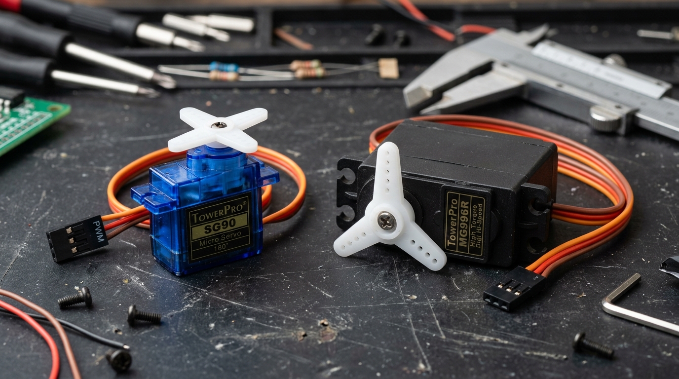
Always choose metal gear servos (like the MG996R or DS3218) for robotic arm joints and walking legs. Plastic gears (like the blue SG90) will easily strip their teeth if the arm bumps into a desk or floor!
6. Motor Drivers & H-Bridges (Power Switchboard)
A common beginner mistake is trying to connect a DC motor directly to an Arduino or ESP32 pin. Never do this!
Why Microcontrollers Need Motor Drivers:
- An Arduino or ESP32 pin can only supply about 0.02 Amps (20 mA) of current.
- A robotic DC motor needs 1.0 to 5.0+ Amps of current from a battery.
- Connecting a motor directly to an Arduino pin will instantly burn out the chip!
- A Motor Driver acts like a heavy-duty switchboard: it takes tiny control signals from your microcontroller and safely switches big battery power to the motors.
How an H-Bridge Works (The 4-Switch Secret):
An H-Bridge circuit arranges 4 electronic switches (MOSFET transistors) in an "H" shape around the motor:
- Forward: Close Switch 1 (Top Left) and Switch 4 (Bottom Right).
- Reverse: Close Switch 2 (Top Right) and Switch 3 (Bottom Left).
- Coast (Freewheel): Open all 4 switches so the motor rolls freely to a stop.
- Active Braking: Close both bottom switches to short the motor coils to ground. The motor's own Back-EMF acts like an instant electronic brake!
Crucial Circuit Protection:
- Flyback Diodes: When a motor suddenly turns off, the collapsing magnetic field creates a huge reverse voltage spike (often 50V–100V!). Flyback diodes safely absorb this spike so your driver doesn't blow up.
- Bulk Capacitors: Place a 470µF to 1000µF capacitor across the motor power inputs to absorb voltage dips and prevent your microcontroller from rebooting.
Avoid outdated L298N drivers which waste 2V to 3V as pure heat. Choose modern MOSFET drivers: TB6612FNG (1.2A), DRV8833 (2A), or BTS7960 (43A) which run cool and deliver 95%+ efficiency.
7. Motor Selection Guide & Practical Formulas
Follow this quick 4-step decision guide when designing your next robot:
- 1Building a Wheeled Rover or Mobile Robot?
- Choose: Geared Brushed DC Motors with rear encoders (for simple rovers) or Geared BLDC Motors (for heavy industrial warehouse rovers).
- 2Building a Drone, Propeller, or High-Speed Rover?
- Choose: Brushless DC (BLDC) Outrunner Motors with an Electronic Speed Controller (ESC).
- 3Building a 3D Printer, CNC Machine, or Precise Slider?
- Choose: Hybrid Bipolar Stepper Motors (NEMA 17) with silent Trinamic TMC2209 microstepping drivers.
- 4Building a Multi-Joint Robotic Arm or Biped Walker?
- Choose: Metal-Gear Servos (for budget 3-DOF arms) or Smart Serial Bus Servos (Dynamixel) for precision joint control.
1. Robot Driving Speed from Motor RPM
A motor spinning at 3,000 RPM with a 30:1 gearbox (output = 100 RPM) and 0.04m (4cm) radius wheels travels at: 100 × (2 × 3.1416 × 0.04) ÷ 60 = 0.42 meters/second (~1.5 km/h).
2. Required Wheel Torque for a Mobile Robot
For a 5 kg robot with 2 drive wheels and 0.05m wheels, accelerating at 1.0 m/s²: Required Torque per wheel = (5 kg × 1.5 m/s² × 0.05 m) ÷ 2 = 0.187 N·m. Always add a 1.5x safety margin (target ≥ 0.28 N·m).
| Motor Type | Cost | Speed Range | Position Precision | Wiring Complexity | Best Use Case |
|---|---|---|---|---|---|
| Brushed DC | Very Low ($) | Medium (3,000 – 10,000 RPM) | Needs External Encoder | Very Simple (2 Wires) | Hobby rovers, simple wheeled robots, conveyor belts |
| Brushless BLDC | Medium ($$) | Ultra High (10k – 50k RPM) | Needs Magnetic Sensor + FOC | Medium (3 Phase + ESC) | Drones, quadrupeds (Spot), high-speed rovers |
| Stepper Motor | Low to Mid ($$) | Low (< 1,500 RPM) | High Open-Loop (0.01°) | Simple (Step + Dir Pins) | 3D printers, CNC axes, precise pan-tilt camera rigs |
| Smart Servo | Mid to High ($$$) | Low (30 – 120 RPM) | Absolute High (12-bit sensor) | Single 3-Wire Daisy Chain | Humanoid joints, 6-DOF robot arms, robotic grippers |
Common Questions & Troubleshooting
Q:Why does my microcontroller (Arduino/ESP32) restart whenever my motors start spinning?
This is called a "Voltage Brownout". When electric motors start from a dead stop, they draw a massive spike of stall current for a few milliseconds. This sudden power surge causes the battery voltage to dip. If the voltage dips below 4.5V/3.0V, your microcontroller resets! To fix this: (1) Use separate battery power or separate DC-DC regulators for motors and logic, (2) Add a 470µF to 1000µF capacitor across the motor driver power pins, and (3) Gradually ramp up motor speed with software acceleration curves instead of jumping instantly to 100% PWM.
Q:What is the difference between Stepper Holding Torque and Running Torque?
Holding Torque is the maximum turning force a stationary, powered stepper motor can resist before its shaft slips out of step. Running Torque is the turning force the stepper can produce while actively spinning. Because coil inductance resists rapid current changes, stepper torque drops sharply as RPM increases!
Q:Why do hobby servos jitter or buzz when holding a position?
Servo jitter is usually caused by: (1) Insufficient power supply current (servos need 1A to 2A burst current; powering multiple servos from an Arduino 5V pin will cause jitter), (2) Electrical noise on the PWM signal wire, or (3) The physical load on the horn is right on the boundary between two encoder positions, causing the internal controller to constantly oscillate back and forth.
Q:How do I choose between an Outrunner and Inrunner BLDC motor?
Choose an Outrunner if you need high torque at moderate RPM to drive drone propellers or direct-drive robotic joints without a gearbox. Choose an Inrunner if you need extreme RPM (15,000+ RPM) coupled with a gearbox or for enclosed ducted fans.