Core Engineering Takeaways
- •Robotics sensors are divided into Internal sensors (measuring wheel spins, tilt, battery voltage) and External sensors (measuring obstacles, distance, camera views).
- •Wheel Encoders measure exact wheel rotation by counting digital pulses, allowing the robot to calculate how far it has driven.
- •MEMS IMUs (like the MPU-6050) combine a 3-axis accelerometer (for tilt/gravity) and a 3-axis gyroscope (for turning speed) to keep robots balanced.
- •Ultrasonic sensors bounce sound waves to detect obstacles within 4 meters; laser ToF sensors use invisible light beams for millimeter accuracy.
- •2D LiDAR spins a laser 360° multiple times per second to create floor maps and help autonomous rovers navigate without bumping into walls.
- •Sensor Fusion blends fast, responsive IMU readings with accurate wheel encoder ticks and LiDAR scans so the robot never gets lost.
- Basic knowledge of Arduino or microcontroller pins
- Understanding of distance (centimeters) and angles (degrees)
1. How Robots Sense the World (Inside vs Outside)
Without sensors, a robot is completely blind. It would crash into walls and flip over. Sensors give robots their senses of touch, balance, and vision!
Robotic sensors are divided into two simple groups:
1. Internal Sensors (Feeling Its Own Body):
- Also called Proprioceptive Sensors.
- Measure what is happening inside the robot.
- Wheel Encoders: Count wheel rotations to know how far the robot traveled.
- IMU (Gyroscope & Accelerometer): Measures balance, tilt, and turning rate.
- Voltage & Current Sensors: Monitor battery level so the robot knows when to recharge.
2. External Sensors (Looking at the Surroundings):
- Also called Exteroceptive Sensors.
- Measure what is happening outside in the room.
- Ultrasonic Sensors: Send sound waves to detect walls and obstacles.
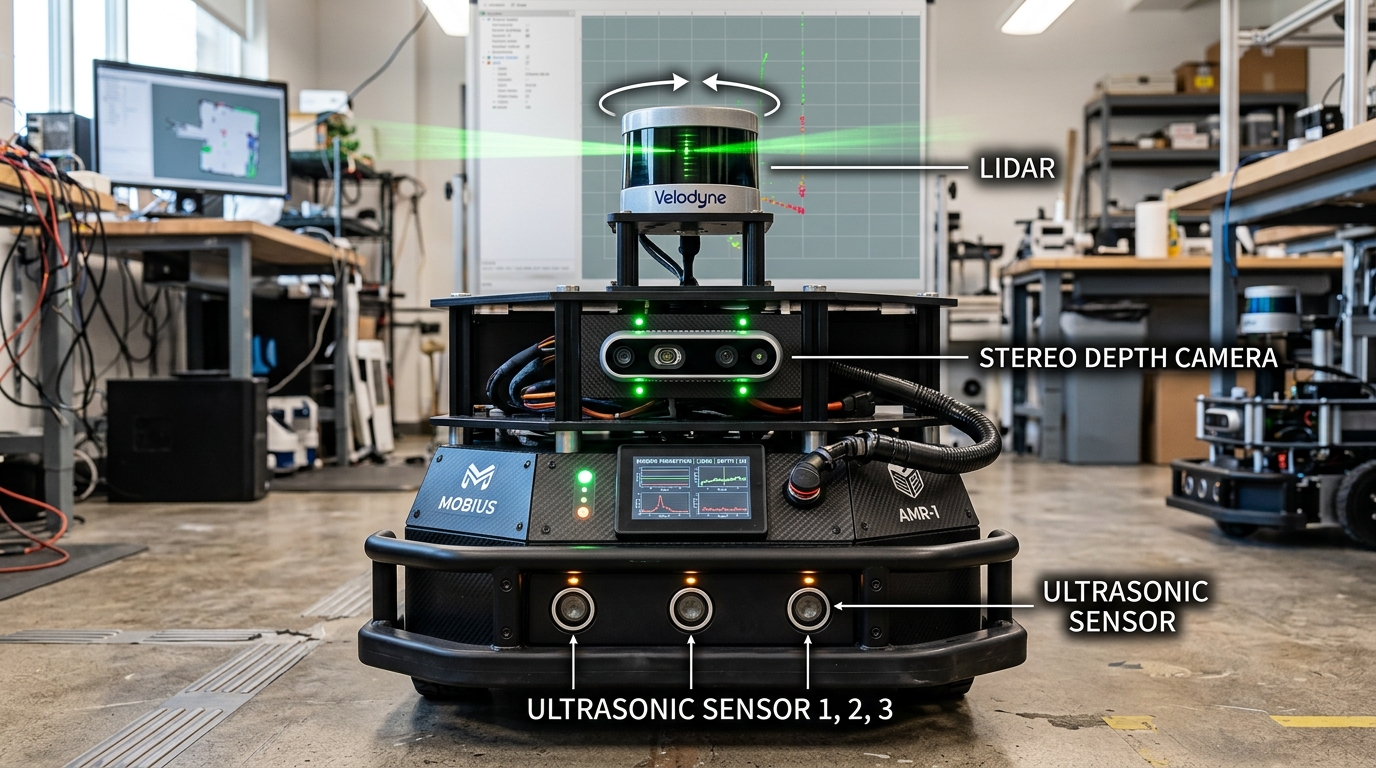
- 2D LiDAR Scanners: Spin laser beams in a 360° circle to create room floor plans.
- Depth Cameras: Capture 3D color images with exact distances for every pixel.
2. Encoders & MPU-6050 Gyro/IMUs (Internal State)
Wheel Encoders (Measuring Distance Driven):
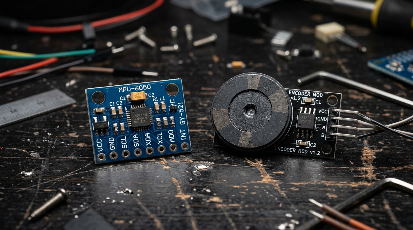
An encoder is mounted behind each motor shaft to count how many times the wheel turns.
- Optical Encoders: A tiny plastic wheel with slots spins between an infrared light and a sensor.
- Magnetic Encoders: A small magnet spins near a hall-effect sensor chip.
- How It Works: Every time the wheel turns, the sensor sends digital pulses (ticks) to the Arduino. If 1,000 ticks equal 1 wheel revolution, 500 ticks mean the robot drove half a turn!
MPU-6050 6-Axis IMU (Balance & Tilt):
An IMU is like the human inner ear—it gives the robot its sense of balance and direction:
- 3-Axis Accelerometer: Measures the downward pull of gravity. It tells the robot if it is tilted forward, backward, or sideways.
- 3-Axis Gyroscope: Measures how fast the robot is actively twisting or spinning in degrees per second.
- Self-Balancing Robots: By reading the accelerometer and gyroscope 100 times a second, a 2-wheeled robot can balance upright without falling!
Wheel Distance Traveled Formula
If a robot with 0.05m radius wheels counts 2,000 ticks on a 1,000 ticks/turn encoder: Distance = (2,000 ÷ 1,000) × (2 × 3.1416 × 0.05) = 0.628 meters traveled.
3. Ultrasonic (HC-SR04) & Laser ToF Distance Sensors
When a robot drives forward, it needs to know if an obstacle is 10cm or 2 meters ahead to stop in time.
Ultrasonic Sensor (HC-SR04):
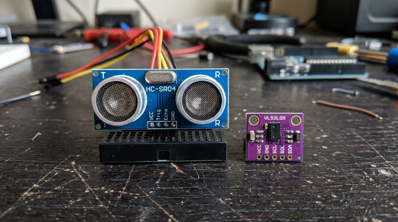
- How It Works: The left silver cylinder emits a burst of 40,000 Hz sound (inaudible to humans). The sound bounces off an obstacle, and the right silver cylinder listens for the echo!
- Range: 2 cm to 400 cm (up to 4 meters).
- Pros: Super cheap ($2), works in total darkness or bright light, detects glass and clear plastic easily.
- Cons: Can bounce away if hitting a wall at a sharp angle or get absorbed by soft rugs and curtains.
Laser Time-of-Flight (VL53L0X):
- How It Works: Fires an invisible laser light pulse and measures the picosecond time it takes light photons to bounce back.
- Range: 3 cm to 200 cm with millimeter accuracy.
- Pros: Extremely tiny (postage stamp size), highly accurate, and narrow beam.
Ultrasonic Distance Calculation
If your Arduino measures an echo time of 1,000 microseconds: Distance = (1,000 × 0.0343) ÷ 2 = 17.15 cm.
4. 2D Rotating LiDAR for Room Mapping (SLAM)
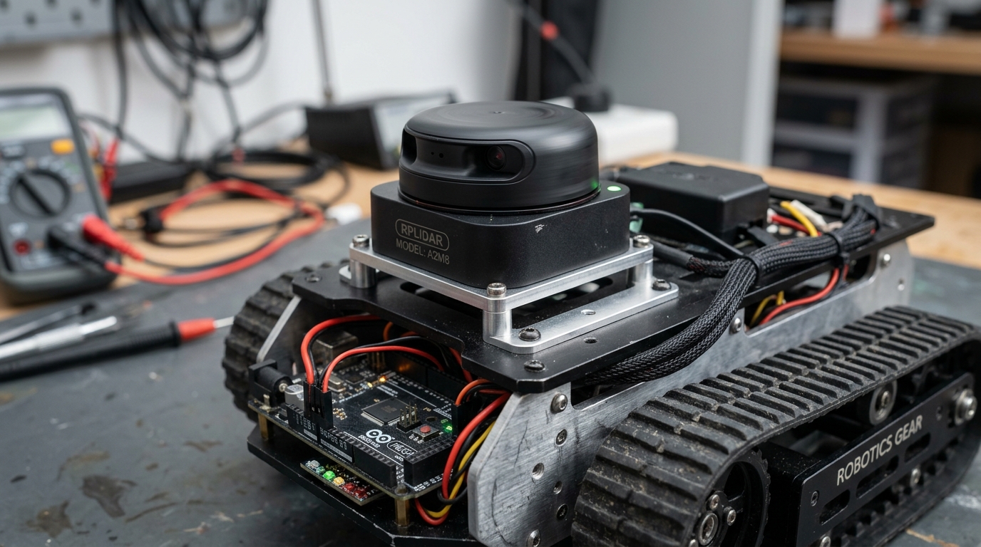
LiDAR stands for Light Detection and Ranging. It is the gold standard sensor used by robotic vacuum cleaners and autonomous warehouse rovers!
How 2D LiDAR Works:
- A small laser module and optical sensor sit on top of a motor that spins 360 degrees, 5 to 10 times every second.
- As it spins, it fires thousands of laser pulses per second in every direction.
- It returns an exact 360° circular outline of all walls, furniture, and obstacles in the room!
What is SLAM? (Simultaneous Localization and Mapping):
- By matching LiDAR scans from one second to the next, the robot draws a 2D floor map of your house while tracking its own exact position on that map.
- This allows smart robot vacuums to clean every room without getting lost!
| Sensor Type | Typical Range | Best Use Case | Lighting Dependency |
|---|---|---|---|
| Ultrasonic (HC-SR04) | 2 cm – 4 meters | Bumper obstacle warning, glass detection | Works in light and total darkness |
| Laser ToF (VL53L0X) | 3 cm – 2 meters | Precise table-edge cliff detection | Works in normal ambient lighting |
| 2D LiDAR (RPLIDAR) | 15 cm – 12 meters | Room mapping (SLAM), autonomous navigation | Works indoors and dim environments |
| 3D Depth Camera | 20 cm – 5 meters | 3D obstacle avoidance, grasping objects | Works indoors and outdoors |
5. RGB-D Depth Cameras (3D Vision for Robots)
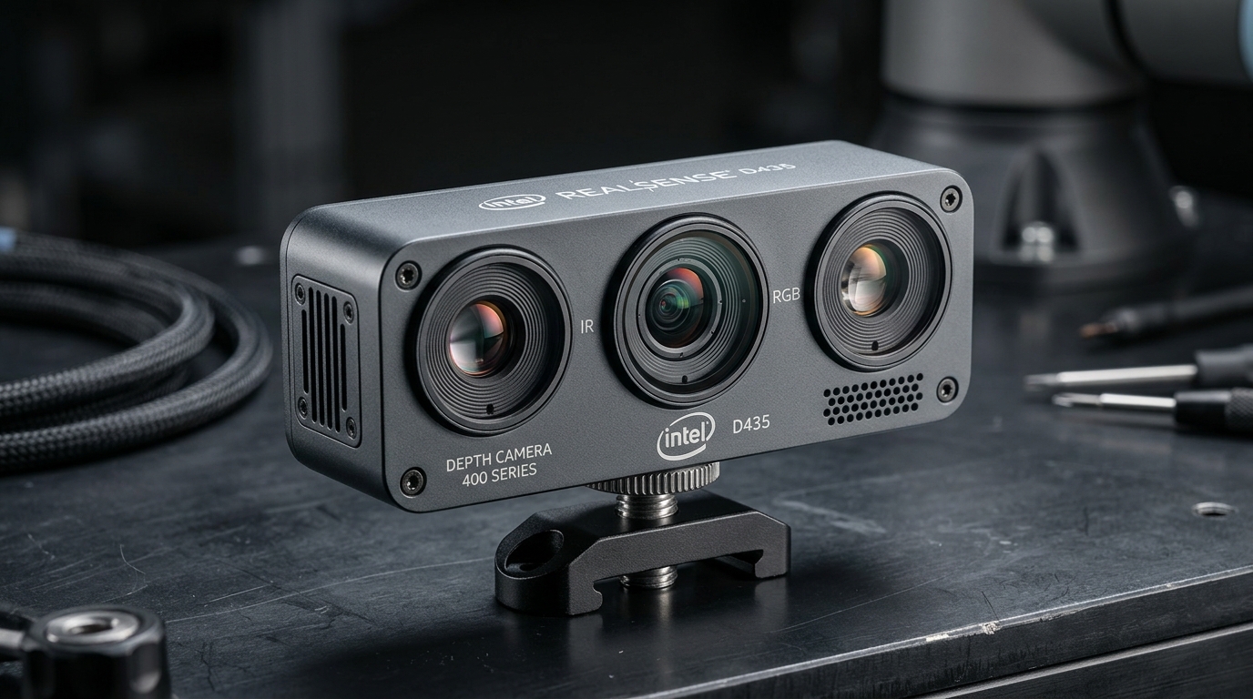
Standard webcams only capture flat 2D color images. A Depth Camera (like the Intel RealSense D435) captures full color plus the exact 3D distance of every single pixel!
How Depth Cameras Work:
- Dual Infrared Eyes: Two cameras look at the scene from slightly different angles (just like your two human eyes).
- Infrared Dot Projector: Casts an invisible pattern of dots onto smooth walls so the cameras can easily measure depth contours.
- Output: Generates a rich 3D Point Cloud showing the exact 3D shapes of tables, boxes, doors, and people!
Where Depth Cameras Are Used:
- Robotic Arms: Finding a coffee mug on a desk and calculating its 3D grip coordinates.
- Autonomous Drones: Avoiding tree branches and thin wires while flying through forests.
- Humanoid Robots: Recognizing human faces and navigating around moving people.
6. Sensor Fusion: Combining Sensors for Pure Accuracy
No single sensor is 100% perfect on its own:
- Wheel encoders slip on smooth floors.
- IMU gyroscopes drift by a few degrees over time.
- LiDAR can get confused in long, empty hallways.
Sensor Fusion is the mathematical trick of combining multiple sensors together so their strengths cancel out their weaknesses!
The Simple Complementary Filter:
On an Arduino, you can fuse an IMU accelerometer and gyroscope in just 1 line of code:
- 98% Gyroscope: Gives instant, rapid response during quick robot turns.
- 2% Accelerometer: Gives a rock-solid gravity reference that constantly wipes away gyro drift.
Result:
You get a silky-smooth, drift-free tilt angle measurement that keeps two-wheeled balancing robots upright for hours!
Simple Complementary Filter Formula
7. Sensor Selection Guide for Robot Builds
Here is a quick cheat-sheet for picking sensors for your robot:
- 1Simple 2-Wheel Line Follower or Rover:
- 2x Infrared line sensors + 1x HC-SR04 ultrasonic distance sensor.
- 2Self-Balancing 2-Wheel Robot:
- 1x MPU-6050 IMU + 2x Wheel encoders.
- 3Autonomous Indoor Room Mapping Robot (SLAM):
- 1x 2D RPLIDAR + 1x 6-axis IMU + 2x Optical/Magnetic wheel encoders.
- 4AI Vision & Gripper Robot Arm:
- 1x Intel RealSense RGB-D depth camera + magnetic joint angle encoders.
| Robot Project | Essential Sensors | Microcontroller / Computer | Primary Task |
|---|---|---|---|
| Obstacle Avoiding Rover | HC-SR04 Ultrasonic or VL53L0X Laser | Arduino Uno / ESP32 | Stop and turn before hitting walls |
| Self-Balancing Robot | MPU-6050 IMU + Dual Encoders | ESP32 / Arduino Nano | 100 Hz balance PID loop |
| Room Mapping SLAM Robot | 2D RPLIDAR + 6-DOF IMU + Wheel Encoders | Raspberry Pi 4/5 or Jetson | Draw 2D floor maps & navigate autonomously |
| Vision AI Robotic Arm | Intel RealSense D435 Depth Camera | Jetson Orin Nano / PC | 3D object detection & pick-and-place |
Common Questions & Troubleshooting
Q:Why does my robot get lost when driving using only wheel encoders (Dead Reckoning)?
Tires have micro-slips on tile and carpet. Even a 2% wheel slip accumulates into a huge error over 10 meters. Always combine encoders with an IMU gyroscope and 2D LiDAR to correct drift.
Q:Can ultrasonic sensors see clear glass doors?
Yes! Ultrasonic sensors use sound waves, which bounce off solid glass just like a brick wall. In contrast, optical laser sensors can pass straight through clean glass, making ultrasonic sensors great safety backups.
Q:What is the easiest IMU for beginners to start with?
The MPU-6050 is the most popular beginner IMU. It is very affordable ($2), widely supported by easy Arduino libraries, and communicates over standard I2C with only 4 wires (VCC, GND, SDA, SCL).