Core Engineering Takeaways
- •Always separate high-current motor power from delicate microcontroller/sensor logic power to prevent reset crashes.
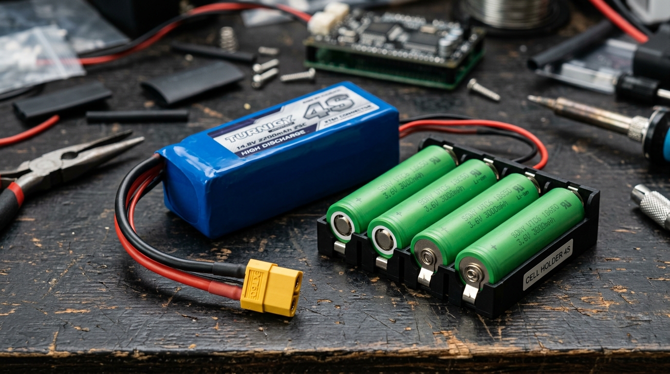
- •LiPo batteries deliver massive burst power for lightweight drones, while 18650 cylindrical cells in steel cans are great for sturdy ground rovers.
- •A Battery Management System (BMS) board is essential—it protects cells from overcharging (>4.2V), overdischarging (<3.0V), and short circuits.
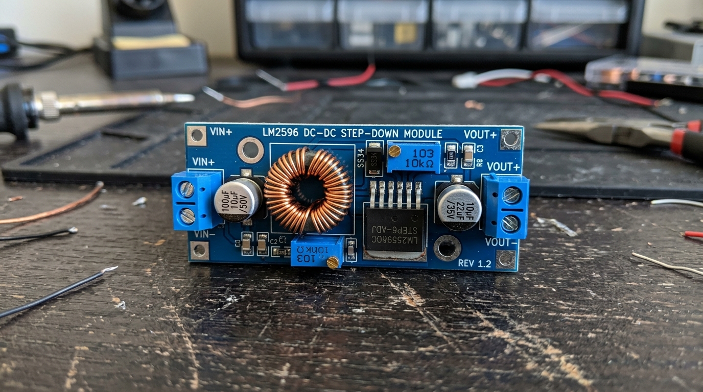
- •Never use linear 7805 regulators for high currents because they waste battery power as pure heat. Always use efficient DC-DC Buck converters (90%+ efficiency).
- •Use Star Grounding: connect all ground wires to one central battery negative point to eliminate electrical motor noise.
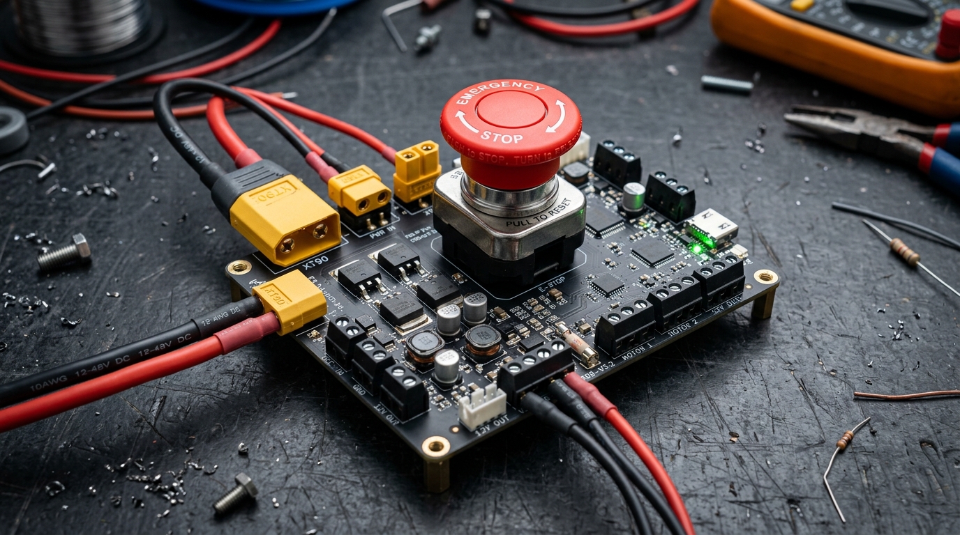
- •Every robot over 2 kg must have a physical, high-visibility red Emergency Stop (E-Stop) button to instantly kill motor power in an emergency.
- Basic electrical terms: Voltage (V), Current (Amps), and Watts (W)
- Understanding of battery positive (+) and negative (-) wires
1. How Robot Power Systems Work (Safe Energy Flow)
A robot's power system is its energy network. A poorly wired power system causes sudden microcontroller resets, motor stuttering, and sensor dropouts!
The Two Power Rails (The Golden Rule):
Never run your Arduino, Raspberry Pi, and motors off the same unbuffered wire. Always split power into two distinct rails:
- 1. The Motor Rail (High Power & Noisy): Powers DC motors, servos, and drivers (e.g. 12V or 24V battery power).
- 2. The Logic Rail (Clean & Regulated): Powers microcontrollers, cameras, and sensors (clean 5.0V or 3.3V power through a DC-DC converter).
Calculating a Simple Power Budget:
Before buying a battery, list your components and their power consumption:
- 2x Geared DC Motors: 12V × 1.5A = 18 Watts
- Raspberry Pi 4 / 5: 5V × 3.0A = 15 Watts
- 2D LiDAR + Sensors: 5V × 1.0A = 5 Watts
- Total Power Consumption: 18W + 15W + 5W = 38 Watts.
Electric Power Formula (Watts)
A 12V robot drawing an average of 3.0 Amps consumes: 12V × 3.0A = 36 Watts of electrical power.
2. Battery Types: LiPo vs 18650 vs LiFePO4
Robots rely on three main rechargeable lithium battery families:
1. Lithium Polymer (LiPo):
- Cell Voltage: 3.7V nominal (4.2V fully charged, 3.3V safe floor).
- Features: Ultra-lightweight foil pouch with huge discharge current (30C to 100C).
- Best For: Drones, combat robots, and agile quadruped robot dogs.
- Caution: Soft foil casing can puncture easily; always charge inside a fire-safe LiPo bag!
2. 18650 / 21700 Cylindrical Li-ion Cells:
- Cell Voltage: 3.6V–3.7V nominal.
- Features: Packaged inside tough steel cylindrical cans that resist physical impacts.
- Best For: Ground rovers, robotic lawnmowers, and modular custom battery packs.
3. Lithium Iron Phosphate (LiFePO4):
- Cell Voltage: 3.2V nominal.
- Features: Extremely safe, non-flammable chemistry with an incredible lifespan of 2,000 to 5,000 charge cycles!
- Best For: Heavy commercial warehouse robots (AMRs) and industrial automated guided vehicles.
| Battery Type | Nominal Cell Volts | Weight / Density | Cycle Lifespan | Best Use Case |
|---|---|---|---|---|
| LiPo (Pouch) | 3.7V per cell | Ultra-Lightweight | 300 – 500 charges | Drones, agile walkers, lightweight robots |
| 18650 (Cylinder) | 3.6V per cell | Compact & Rugged | 500 – 1,000 charges | Mobile rovers, modular battery packs |
| LiFePO4 | 3.2V per cell | Medium Weight | 2,000 – 5,000 charges | Heavy warehouse AGVs, industrial robots |
3. Battery Capacity, C-Ratings & Runtime Formulas
What is the "C-Rating"?
The C-Rating printed on a battery tells you how fast it can safely discharge electricity without overheating.
- Formula: Maximum Safe Current (Amps) = C-Rating × Capacity in Ah
- Example: A 2200 mAh (2.2 Ah) battery with a 30C rating can safely deliver:
30 × 2.2 Ah = 66 Amps continuous discharge!
Estimating Robot Runtime:
To calculate how many hours your robot will run on a full charge, take total Watt-hours and divide by average power consumption.
1. Max Safe Current (C-Rating)
A 5000 mAh (5.0 Ah) battery rated at 20C can output: 20 × 5.0 Ah = 100 Amps safely.
2. Robot Battery Runtime Formula
A 12V 5Ah battery (60 Wh) powering a 15 Watt robot runs for: (60 Wh × 0.80) ÷ 15W = 3.2 hours of drive time!
4. BMS Protection Boards (Why Batteries Need Them)
A multi-cell battery (like a 3S 11.1V or 4S 14.8V pack) is built from individual 3.7V cells wired in series. Because no two cells are 100% identical, one cell will always empty or fill faster than the others.
A BMS (Battery Management System) is a small electronic circuit board soldered directly to your battery pack.
The 4 Jobs of a BMS:
- 1Overcharge Cutoff: Stops charging immediately if any single cell reaches 4.25V.
- 2Overdischarge Cutoff: Disconnects power if any single cell drops below 3.0V.
- 3Short-Circuit Protection: Instantly cuts power in microseconds if positive and negative wires accidentally touch!
- 4Cell Balancing: Bleeds excess energy off higher cells during charging so all cells stay perfectly equalized.
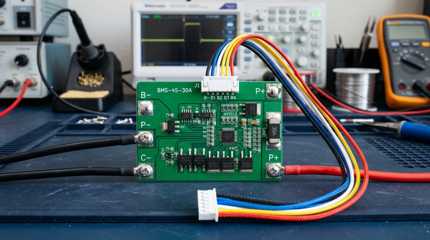
Always use a BMS board on DIY battery packs. Without a BMS, a single weak cell can drop below 2.5V and catch fire during the next charge cycle!
5. DC-DC Step-Down (Buck) Regulators (5V/12V Power)
You cannot connect a 12V or 24V motor battery directly to a 5V Raspberry Pi or 3.3V ESP32 microcontroller without blowing it up. You need a voltage regulator.
The Mistake: Old Linear Regulators (LM7805):
- Linear regulators work by acting like a resistor that turns all excess voltage into pure waste heat!
- Stepping 12V down to 5V at 2A creates 14 Watts of heat—the chip will burn your fingers and drain your battery in minutes.
The Solution: Switch-Mode DC-DC Buck Converters:
- LM2596 / XL4015 Buck Converters: Chop incoming voltage rapidly using high-speed MOSFETs and smooth it through an inductor.
- Over 90% Efficiency: Stays cool and wastes almost zero battery energy!
- Adjustable Voltage: Turn the small brass screw on the blue potentiometer to dial in exactly 5.0V for your Raspberry Pi or 6.0V for your servo motors.
6. Power Distribution Boards (PDB) & Star Grounding
A Power Distribution Board (PDB) acts like the main electrical fuse box in your home, routing battery power safely to motors, regulators, and sensors.
The "Star Grounding" Rule:
When big DC motors start spinning, they pull heavy electrical surges that create noise on ground wires. If your Arduino shares a daisy-chained ground wire with a motor, this electrical noise can make your microcontroller freeze or reboot!
The Solution: Star Grounding Run a separate ground wire from every single component directly back to one central ground terminal right at the battery.
Safe Connectors:
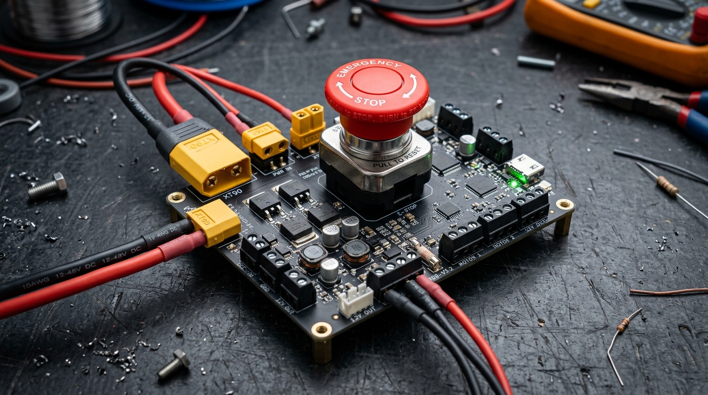
- XT30 / XT60 / XT90: High-quality gold-plated yellow connectors that lock tightly, prevent reverse polarity, and never vibrate loose during robot driving.
7. Emergency Stop (E-Stop) & Safe Wiring Rules
Safety is the most important part of robotics. Every robot with powerful motors must have an easy-to-hit Emergency Stop button!
Emergency Stop (E-Stop) Rules:
- Big Red Mushroom Button: Mount a large, bright red twist-to-release button on the top outside of your robot.
- Fail-Safe Normally Closed (NC): Wire the button so that pressing it physically breaks the main battery circuit immediately.
- Fuse Protection: Always place an automotive blade fuse (e.g. 15A or 30A) right next to the battery positive terminal to protect against short-circuit fires.
| Wire Gauge (AWG) | Max Safe Current | Recommended Use in Robotics |
|---|---|---|
| 12 AWG | 30 – 40 Amps | Main battery cables and high-power motor drivers |
| 16 AWG | 12 – 18 Amps | Individual DC motor connections |
| 20 AWG | 4 – 6 Amps | Raspberry Pi / Jetson 5V power input lines |
| 24 AWG | 1 – 2 Amps | Sensor signals, I2C, SPI, and Arduino logic pins |
Common Questions & Troubleshooting
Q:Why does my microcontroller reset when my robot starts moving?
This is called a "Voltage Brownout". When electric motors start from a standstill, they pull a huge surge of stall current, making battery voltage dip for a split second. If this dip drops below 4.5V, your microcontroller restarts! Fix this by: (1) Using a dedicated DC-DC Buck converter for your computer, (2) Adding a 1000µF capacitor across the power input, and (3) Gradually ramping motor speed up in software.
Q:Can I charge a LiPo battery with a standard bench power supply?
No! A bench power supply cannot balance individual cells. Over repeated charges, one cell will overcharge past 4.2V and can catch fire. Always use a dedicated microprocessor balance charger (like ISDT, SkyRC, or ToolkitRC).
Q:What is the difference between Ah and Wh on a battery?
Ah (Ampere-hours) only measures electrical charge capacity without considering voltage. Wh (Watt-hours) measures true energy: Energy = Voltage × Ah. A 24V 5Ah battery stores 120 Wh—twice as much energy as a 12V 5Ah battery (60 Wh)!